Dorelink
Dorelink
Dorelink
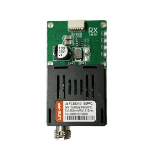
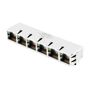
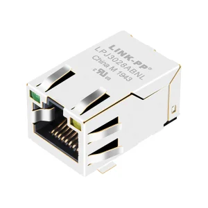
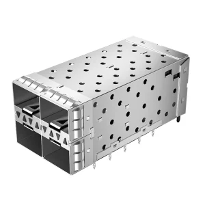
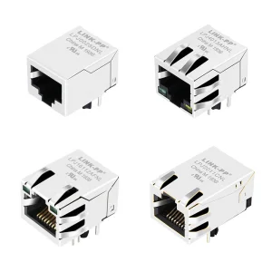
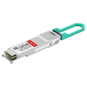
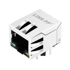
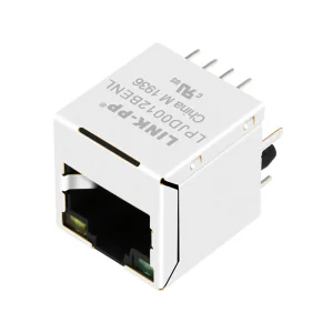
Explore our top-performing optoelectronic components, active optical transceivers, and high-speed magjack connectors deployed in enterprise networks worldwide.
An engineering analysis of FTTx propagation, signal division mechanisms, and critical optoelectronic parameters in modern optical networks.
In modern telecommunications, the Passive Optical Network (PON) has emerged as the definitive standard for delivering high-bandwidth connectivity to end-users. The performance of these networks hinges on passive optical splitters—devices that divide optical power from a single input fiber into multiple output paths. As operators scale from GPON to XGS-PON and toward 50G-PON, understanding the structural dynamics of optical splitters becomes critical.
Optical splitters primarily fall into two technologies: Planar Lightwave Circuit (PLC) splitters and Fused Biconical Taper (FBT) splitters. Each uses a distinct manufacturing approach that affects its operating wavelength, split ratio capability, and environmental stability.
PLC splitters are fabricated using semiconductor-style photolithography on silica glass substrates, creating high-precision waveguides that split light uniformly across all output channels. FBT splitters are manufactured by twisting and fusing two or more fibers together under tension. The table below outlines the core performance differences between these two technologies:
| Performance Parameter | PLC Splitter Technology | FBT Splitter Technology |
|---|---|---|
| Operating Wavelength Range | Wideband (1260 nm – 1650 nm) | Narrowband (1310/1490/1550 nm window) |
| Maximum Split Ratio | Up to 1:64 or 1:128 per chip | Typically limited to 1:4 (custom configuration) |
| Uniformity of Power Division | High uniformity (< 0.8 dB deviation) | Variable, dependent on coupling geometry |
| Temperature Sensitivity | Excellent (-40°C to +85°C stability) | Higher drift, susceptible to thermal changes |
| Package Dimensions | Compact, high-density configurations | Larger footprint at high split ratios |
For high-density fiber management systems, PLC splitters are the industry choice for FTTH, FTTC, and FTTB deployments. Their ability to deliver low insertion loss and minimal polarization-dependent loss (PDL) across the entire O-band through L-band ensures compatibility with multiplexed systems, including WDM-PON configurations.
Technical standards and performance metrics required to optimize Return on Investment (ROI) and minimize operational downtime.
Insertion loss is the primary factor limiting the reach of an optical distribution network (ODN). Procurement guidelines should specify max IL limits: ≤3.8 dB for 1:2 splitters, ≤10.5 dB for 1:8, and ≤20.5 dB for 1:64 configurations, ensuring the optical power budget remains within acceptable levels.
Reflections back toward the optical source can degrade transmitter performance. Standard PLC splitters must meet return loss criteria of ≥55 dB for UPC finishes, and ≥65 dB for APC (Angled Physical Contact) finishes, which helps prevent signal noise and laser instability.
Polarization Dependent Loss (PDL) measures the variation in insertion loss across different polarization states. For high-rate optical transmissions, PDL must be kept below 0.2 dB for 1:2 splits and below 0.4 dB for 1:64 splits to avoid polarization-mode dispersion (PMD) issues.
How optical splitters are deployed across various network architectures to support high-density routing and distribution.
In large-scale networking, optical splitters act as the foundational routing hubs of the passive infrastructure. The design of these solutions varies depending on the specific network topology and physical environment:
In centralized configurations, splitters are housed in a single location, such as a local convergence cabinet or central office. This setup typically uses 1:32 or 1:64 split ratios, routing fiber directly to individual homes. This architecture simplifies troubleshooting, centralizes testing points, and reduces passive component costs across the network.
Cascaded splitting topologies distribute the split ratios across multiple locations. For example, a 1:4 primary splitter in a local closure might feed into four separate 1:8 secondary splitters located closer to the subscriber premises. This approach reduces the total amount of distribution fiber required, making it ideal for rural deployments and areas with high civil engineering costs.
In hyperscale data centers, splitters are configured as optical taps to monitor network traffic. By splitting off a small portion of the optical signal (e.g., a 90:10 or 80:20 ratio), monitoring equipment can analyze traffic in real-time without disrupting primary data streams. These splitters are typically housed in high-density 19-inch rack-mount chassis to optimize rack space.
Next-generation physical layer innovations supporting high-density optical routing and silicon photonics integration.
Co-packaging optical engines directly with ASICs helps reduce trace lengths and parasitic losses. Future PLC structures will be integrated onto silicon chips to support direct fiber-to-silicon coupling.
As multi-core fibers move from research labs to commercial networks, optical splitters must adapt to process multiple spatial modes in a single fiber core without cross-talk.
With the deployment of multi-band wavelength division multiplexing, splitters must maintain uniform attenuation profiles across all transmission bands, spanning 1260 nm to 1675 nm.
An overview of our quality control protocols, verification testing, and compliance certifications for international telecommunications markets.
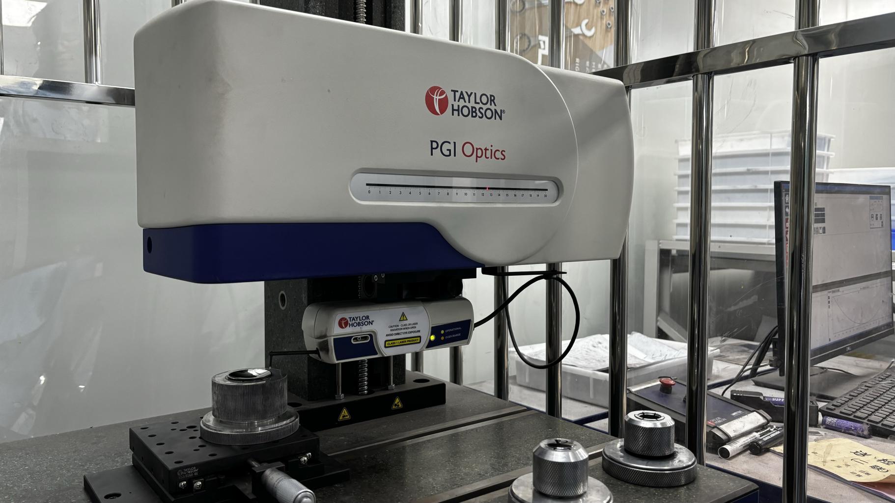
To ensure long-term reliability in varying environmental conditions, optical passives must undergo extensive stress testing. Our quality control processes are structured around Telcordia standards, which serve as the benchmark for telecom operations globally:
Every batch of splitters undergoes optical performance testing on high-precision instrumentation, with individual test reports provided for insertion loss, return loss, and PDL across the selected operating window. This level of quality verification minimizes installation failures and reduces maintenance overhead for network operators.
Answers to common technical questions regarding passive optical components and network deployments.
PDL measures the variation in insertion loss caused by changing polarization states in the optical signal. In high-speed, long-distance systems, excessive PDL can cause signal fluctuations and increase the bit error rate (BER). High-quality PLC splitters maintain a PDL below 0.3 dB to keep signal degradation to a minimum.
FTTH GPON networks generally use a total split ratio of 1:64 or 1:32. This can be achieved through a single-stage split (e.g., one 1:64 splitter in a central cabinet) or a two-stage split (e.g., a 1:8 primary split followed by a 1:8 secondary split in the field).
APC (Angled Physical Contact) connectors feature an 8-degree angled ferrule face, which reflects return light out into the fiber cladding rather than back toward the transmitter. This results in a higher return loss (≥65 dB compared to ≥55 dB for UPC), which is critical for analog RF video signals and high-speed data transmission.
Yes, PLC splitters designed for outdoor use are built to meet Telcordia GR-1221-CORE specifications. They feature sealed packaging and rugged optical fiber buffer tubes, allowing them to operate reliably in outdoor enclosures across temperatures ranging from -40°C to +85°C.
The theoretical minimum insertion loss for a 1:16 split is 12 dB (based on 10*log10(16)). In practice, accounting for fiber attenuation, waveguide loss, and connector mating loss, a standard 1:16 PLC splitter typically has an insertion loss between 13.5 dB and 14.0 dB.
Corporate Profile, Production Capacity, and Quality Standards.
Dorelink Optical Communications Co., Ltd. was established in 2016 and specializes in the research, development, manufacturing, and global supply of high-performance optical transceiver products. With a strong focus on optical communication technologies, Dorelink provides reliable fiber optic solutions for data centers, telecommunications networks, enterprise connectivity, and industrial applications.
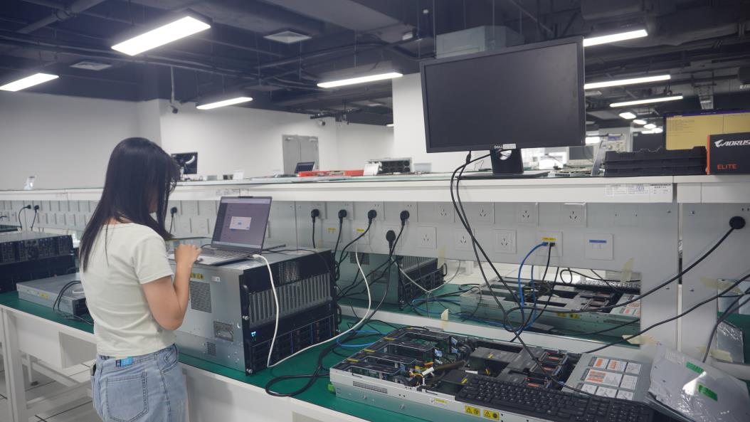
The company operates a modern manufacturing facility with a total building area of 18,500㎡, equipped with advanced production lines, automated testing equipment, and professional optical module assembly facilities. Dorelink has achieved an annual export revenue of approximately USD 18 million, supported by years of international market experience and a stable global customer network.
Dorelink implements a comprehensive quality management system covering raw material inspection, production monitoring, optical performance testing, reliability verification, and final product evaluation.
Dorelink exports optical transceiver products to customers worldwide and has developed strong partnerships across multiple regions.
Dorelink maintains a strong research and development team dedicated to optical communication innovation, product optimization, and customized solutions.
With continuous investment in technology development and manufacturing capabilities, Dorelink Optical Communications Co., Ltd. is committed to delivering high-quality optical transceiver solutions and building long-term partnerships with customers worldwide.


Explore our full line of active optical transceivers, network interface accessories, and magnetic connectors designed to support next-generation telecom standards.