Dorelink Dorelink

What Are the Best CWDM Transceiver Types in 2026?

Time:2026-10-14 Author:Liam
0%

Choosing the best CWDM transceiver in 2026 requires more than comparing data rates. The real decision depends on fiber distance, channel wavelength, switch compatibility, and operating conditions. A 10G SFP+ may suit a regional link, while a 25G SFP28 can better support growing data-center traffic. Some networks still need dependable 1G modules. Others require higher density and stronger diagnostic features.

Dr. Peter Winzer, a recognized optical-communications expert, has emphasized a useful engineering principle: “Design the complete optical system, not the transceiver alone.” That idea remains practical. A module can meet its advertised reach, yet perform poorly with high-loss connectors, aging fiber, or unsuitable patch panels. Engineers should check wavelength plans, insertion loss, dispersion, DOM monitoring, temperature ratings, and vendor interoperability before ordering.

This guide examines the leading CWDM transceiver types expected to matter in 2026. It compares SFP, SFP+, SFP28, and higher-density form factors. It also considers fixed-wavelength and tunable options. The best choice is not always the newest one. Sometimes, a proven 10G module offers lower risk and simpler maintenance. That can be easy to overlook.

Field experience also reveals an uncomfortable truth. Datasheets rarely show the entire installation story. Connector cleanliness, thermal airflow, and firmware behavior can change results. Therefore, readers should treat reach claims as planning values, not promises. This article offers a practical framework for selecting reliable CWDM transceiver solutions, while acknowledging that every network has imperfect constraints.
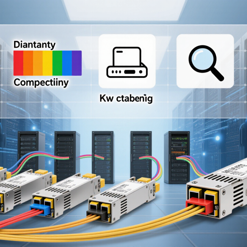
What Are the Best CWDM Transceiver Types in 2026?

CWDM Transceivers: Definition, Purpose, and Core Components

CWDM transceivers are optical modules that send and receive data over separate wavelengths on one fiber pair. CWDM means Coarse Wavelength Division Multiplexing. It uses wider channel spacing than dense systems, making the design simpler and more tolerant of wavelength drift. Typical channels sit across the 1270–1610 nm range. The exact range depends on the fiber plant and regional network plan.

Their purpose is practical. Several services can share one fiber route without installing new cable. A transceiver converts electrical signals into optical pulses, then changes incoming light back into data.

Common types include SFP, SFP+, SFP28, and QSFP modules. Selection depends on speed, reach, connector type, and whether the link uses duplex or BiDi transmission.

A short data-center link needs different performance from a 40-kilometer metro connection.

The core components include a laser transmitter, photodiode receiver, transimpedance amplifier, clock recovery circuit, monitoring sensor, and management memory. Some designs also use temperature control to stabilize output power.

Passive CWDM multiplexers and demultiplexers combine or separate wavelengths outside the module.

In practice, these parts matter more than the housing label. A module may fit the port yet fail because of power limits, optical budget, or incorrect channel pairing. This is where specifications can mislead.

Field checks should include received power, connector cleanliness, fiber loss, and digital diagnostics before deployment. Even experienced teams sometimes overlook dispersion or aging connectors. Those small errors become expensive at scale.

Major CWDM Transceiver Types by Form Factor and Data Rate

What Are the Best CWDM Transceiver Types in 2026?

CWDM transceivers are selected mainly by form factor, channel count, and data rate. Small-form-factor pluggables remain practical for 1G and 10G links. SFP modules fit compact switches and access networks. SFP+ supports 10Gbps, while SFP28 commonly handles 25Gbps over single-mode fiber. The 20nm channel spacing defined in ITU-T G.694.1 helps reduce wavelength-management complexity.

For higher capacity, QSFP+ supports 40Gbps through four lanes. QSFP28 typically delivers 100Gbps, often using four 25Gbps lanes. Newer QSFP56 designs can reach 200Gbps, but CWDM compatibility depends on optical architecture and host equipment. LightCounting’s 2024 optical transceiver market analysis shows strong demand for higher-speed pluggable optics as data-center traffic expands. The report also indicates that 400G and faster segments are gaining attention, although they are not always the best fit for conventional CWDM deployments.

Form factor affects installation as much as speed. A compact SFP28 may suit a metro access cabinet with limited power and airflow. A QSFP28 can reduce port usage in a crowded aggregation rack. Real deployment experience still matters. Temperature, fiber length, connector loss, and switch coding can change the result. Some specifications look impressive on paper. They may disappoint in mixed-vendor networks. Dell’Oro Group’s Ethernet switching forecasts also point toward continued bandwidth growth, but planners should avoid buying the highest rate automatically. Sometimes, 10G remains the more reliable and economical choice.

How Wavelength, Transmission Distance, and Fiber Count Differ

Choosing a CWDM transceiver in 2026 starts with the optical path, not the data rate alone. CWDM modules use separated wavelengths across one fiber pair, allowing several channels to share existing cable. Common options include 10G, 25G, and higher-speed variants, but compatibility depends on port coding, wavelength range, and link budget. In field deployments, I check the patch panel, connector condition, and measured loss before selecting a module. A specification sheet cannot reveal a dirty connector.

Wavelength determines channel placement and influences how the signal behaves across the fiber. Shorter wavelengths may suit shorter campus links, while longer wavelengths often support extended reaches. Yet distance labels can mislead. A “40 km” optic may fail when splices, bends, or aging panels consume the margin. Calculate total attenuation, then reserve practical headroom. This is where many designs become optimistic.

Fiber count changes the architecture. A two-fiber CWDM system uses one fiber for transmit and another for receive. Bi-directional designs can send both directions over one fiber, but they require matched wavelength plans and stricter maintenance. Single-fiber operation saves cable capacity, not necessarily troubleshooting time. I have seen installations pass initial tests and struggle later because spare wavelengths were ignored. Leave room for growth, document every channel, and verify actual power levels after installation. The perfect type does not exist.

What Are the Best CWDM Transceiver Types in 2026? — How Wavelength, Transmission Distance, and Fiber Count Differ
CWDM Transceiver Type Typical Data Rate Nominal Wavelength or Wavelength Set Typical Transmission Distance Fiber Count Common Fiber and Connector Typical Application
1G CWDM Single-Wavelength 1.25 Gb/s One channel within the 1271–1611 nm CWDM grid; 20 nm channel spacing Up to 10 km, 40 km, or 80 km depending on optical budget 2 fibers for duplex operation; 1 fiber for BiDi designs Duplex single-mode fiber; usually duplex LC Campus networks, access aggregation, and legacy Gigabit Ethernet links
10G CWDM Short-Reach 10.3125 Gb/s One CWDM channel, commonly selected from 1271–1611 nm Up to 10 km 2 fibers; 1 fiber only when a BiDi variant is used Single-mode fiber; duplex LC is common Data-center interconnects and metropolitan Ethernet access
10G CWDM Extended-Reach 10.3125 Gb/s One CWDM channel from the 20 nm ITU-T grid Up to 40 km or 80 km, subject to power budget and dispersion limits 2 fibers Duplex single-mode fiber; duplex LC Longer metropolitan links and distributed enterprise campuses
25G CWDM 25.78125 Gb/s One channel, typically within the 1271–1571 nm portion of the CWDM grid Up to 10 km; longer distances require a higher optical budget or a different optic class 2 fibers Single-mode fiber; duplex LC 25GbE leaf-spine links, access aggregation, and mobile transport
40G CWDM4 / LR4 41.25 Gb/s aggregate Four lanes near 1271, 1291, 1311, and 1331 nm Up to 2 km for CWDM4; up to 10 km for LR4-class implementations 2 fibers, with four wavelengths multiplexed over the pair Parallel single-mode optical lanes internally; duplex LC externally 40GbE data-center interconnects and short metropolitan links
100G CWDM4 103.125 Gb/s aggregate Four wavelengths near 1271, 1291, 1311, and 1331 nm Up to 2 km 2 fibers Single-mode fiber; duplex LC High-density data-center leaf-spine and server-area interconnects
100G 4WDM-10 103.125 Gb/s aggregate Four CWDM wavelengths, commonly around 1271, 1291, 1311, and 1331 nm Up to 10 km 2 fibers Single-mode fiber; duplex LC Metro data-center interconnects and extended 100GbE campus links
100G 4WDM-20 103.125 Gb/s aggregate Four CWDM wavelengths with approximately 20 nm spacing Up to 20 km when the required optical budget is supported 2 fibers Single-mode fiber; duplex LC Longer-reach metropolitan and regional aggregation
100G Single-Wavelength CWDM 100 Gb/s One selected wavelength in the CWDM grid; implementation-dependent Typically 10–40 km depending on modulation, optics, and link budget 2 fibers; single-fiber versions require matched BiDi optics Single-mode fiber; duplex LC or a duplex multifiber interface Simple wavelength-based upgrades where four-lane CWDM is unnecessary
CWDM BiDi Transceiver 1G, 10G, or 25G commonly available Two complementary wavelengths, one for each transmission direction Typically 10–40 km; some 1G versions reach 80 km 1 fiber Single-mode fiber; simplex LC is common Fiber-constrained networks where a second strand is unavailable
CWDM Mux/Demux with Transceivers Multiple services from 1G to 100G Up to 18 standard CWDM channels from 1271 to 1611 nm at 20 nm spacing Commonly 40–80 km, subject to insertion loss, dispersion, and transceiver budget 2 trunk fibers for duplex aggregation; each client port normally uses 2 fibers Single-mode fiber; LC client ports and LC/SC trunk options High-capacity metro networks that combine multiple protocols over one fiber pair
Note: Transmission distances are representative maximum reaches for common CWDM deployments, not universal guarantees. Actual reach depends on transceiver optical power, receiver sensitivity, connector and splice loss, chromatic dispersion, fiber type, temperature range, and the insertion loss of the CWDM multiplexer or demultiplexer. The standard CWDM wavelength grid uses 20 nm spacing; the exact channel availability depends on the optical design and network budget.

Comparing CWDM Transceivers for Common Network Applications

CWDM transceiver selection should match the network’s distance, capacity, and fiber condition. ITU-T G.694.2 defines a 20 nm channel grid, commonly supporting up to 18 wavelengths from 1271 nm to 1611 nm. For campus links, 1G and 10G CWDM SFP modules remain practical. They fit existing switch ports and typically serve connections from several kilometers to metropolitan distances. For heavier aggregation, 25G SFP28 and 100G QSFP28 CWDM options reduce port consumption. The right choice depends on reach and optical budget, not speed alone.

Cisco’s Annual Internet Report projected global IP traffic to reach 396 exabytes per month by 2022, increasing pressure on access and aggregation networks. That growth makes 100G CWDM attractive for short data center interconnects, especially where fiber pairs are scarce. However, 100G modules often use four wavelengths and require clean connectors, matched fiber paths, and careful power-budget checks. A 10G module can be more economical for branch or enterprise links. It is not automatically outdated.

In practical deployments, technicians should verify DOM readings, connector loss, and temperature range before selecting a transceiver. Industrial environments may need extended-temperature versions. Standard-temperature modules can fail earlier in poorly ventilated cabinets. This detail is often overlooked. A 2 km CWDM module may also be unsuitable when patch panels add unexpected loss. Dell’Oro Group’s optical networking research continues to show strong demand for higher-capacity network infrastructure, yet capacity forecasts do not replace site measurements. Real fiber conditions still decide performance.

Choosing a CWDM Transceiver Based on Compatibility and Scalability

Choosing the best CWDM transceiver in 2026 starts with compatibility, not headline speed. ITU-T G.694.2 defines an 18-channel CWDM grid, spaced at 20 nm from 1271 to 1611 nm. This wide spacing supports practical temperature tolerance and lower-cost optics. However, every wavelength must match the existing multiplexer, fiber route, and optical budget. A 10G module may fit physically but fail operationally if its coding, connector, or reach specification differs.

Read the equipment data sheet carefully.

Industry planning supports a scalable approach. The 2024 Ethernet Alliance roadmap highlights 400G and 800G interfaces as important paths for growing data-center networks. That does not make high-speed CWDM suitable everywhere. For short links, simple duplex CWDM optics may remain more efficient. For expansion, choose modules with digital diagnostics, extended temperature options, and documented interoperability. These features help technicians monitor receive power, temperature, and wavelength drift before a failure becomes visible.

Field testing still matters. A module can pass a basic link test and struggle after patch-panel additions or aging connectors. I have found that power-margin calculations are often too optimistic. Leave measurable headroom, verify actual insertion loss, and test every wavelength under operating conditions. Scalability is not just higher bandwidth; it is preserving compatibility when the network grows.

FAQS

What is a CWDM transceiver?

It sends and receives data using separate wavelengths over one fiber pair. CWDM means Coarse Wavelength Division Multiplexing. Its wider channel spacing simplifies wavelength management.

Why use CWDM transceivers?

Several services can share existing fiber without installing new cable. This saves cable space and may reduce deployment work. The savings depend on installation conditions.

Which form factors are commonly available?

Common options include SFP, SFP+, SFP28, QSFP+, QSFP28, and QSFP56. SFP suits lower speeds, while QSFP models support higher capacity. The host port must support the selected module.

How should I choose the transmission speed?

Match the module to actual traffic, reach, and switch compatibility. SFP+ often supports 10Gbps, while SFP28 commonly supports 25Gbps. Buying the fastest option is not always wise.

What distance can a CWDM transceiver support?

Distance depends on wavelength, fiber quality, splices, bends, and connector loss. A listed 40-kilometer reach may fail without enough optical margin. Calculate total attenuation before installation.

Does wavelength affect performance?

Yes. CWDM channels commonly occupy the 1270–1610 nm range. Shorter wavelengths may suit shorter links, while longer wavelengths can support extended reaches. The exact plan depends on the fiber network.

Can CWDM work over one fiber?

Yes, BiDi designs can transmit both directions over one fiber. They require matched wavelength pairs and careful channel planning. One fiber saves capacity, not troubleshooting time.

What components are inside a CWDM transceiver?

Key parts include a laser, photodiode, amplifier, clock recovery circuit, monitoring sensor, and management memory. Some modules add temperature control. The housing label tells very little.

What should I check before deployment?

Check received power, connector cleanliness, fiber loss, channel pairing, and diagnostic readings. Inspect the patch panel closely. A dirty connector can defeat an impressive specification.

What mistakes commonly affect CWDM links?

Teams may overlook dispersion, aging connectors, spare wavelengths, or switch coding. I might also miss a small loss during planning. Document every channel and recheck power after installation.

Conclusion

CWDM transceivers are optical networking devices that combine electrical data signals with selected wavelengths of light, allowing multiple channels to travel over a single fiber pair. Their main components typically include an optical transmitter, receiver, wavelength filter, and electrical interface. The best CWDM transceiver type depends on factors such as form factor, data rate, wavelength range, and transmission distance. Common options vary from compact modules for space-limited equipment to higher-capacity designs for aggregation and transport networks.

When comparing CWDM transceivers, network planners should consider fiber count, reach requirements, connector design, and compatibility with switches, routers, and multiplexing equipment. Lower-rate modules may suit access links, while higher-rate options are better for data center interconnection and metropolitan networks. A practical choice should also support future expansion, consistent optical performance, and straightforward management. By matching wavelength, distance, and interface specifications with current and expected traffic needs, organizations can build a scalable and cost-efficient fiber network.

Liam

Liam

Liam is a dedicated marketing professional with a profound expertise in the industry, where he excels at highlighting the unique advantages of our core products. With a keen understanding of market trends and consumer needs, Liam frequently updates our company’s professional blog, providing......